Example of Handling and Developing of a Microflame Soldering Application
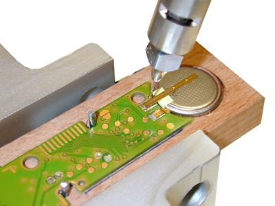
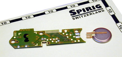
A small battery cell shall be soldered leads flat to the pads on a printed circuit board as shown to the right.
Basic idea:
In a first design approach the parts (cell and pc) shall be manually placed into 'nests' on a rotary table . Then they are cycled through various automation stages, an important one being the soldering station. As process gets a grip on parameters additional automation steps will be integrated.
The demand for a <0 failure> level dictates the use of the Spirflame® microflame soldering technique. The heat transfer from a spirflame® to heated parts is always identical and and it is a non-contact heat transfer.
Considerations using electric irons:
- Oxide layers on tip?
- mechanical contact pressure tip to component?
- gap between part and tip filled with solder for good heat transfer?
Considerations using light or laser beams:
- Variations in reflexivity of taget surface do immediatelly reflect in temperature changes there.
- Evaporating solvent / binder 'clouds' from flux interfer with transmission like a cloud layer to sunlight,
How to develop the process parameters?
Experimental trials shall start with unpopulated boards. This simplifies making simple experimental fixtures and jigs.
Microflame soldering demands a precise, defined and repetitive parts positioning, just as with other processes. The flame shall be able to deliver its heat energy always to the same location. Target versus flame position variations would otherwise cause variations in temperature levels on target.
Manual handling of flame soldering should be avoided. Manual handling tolerances of experiments are simply too erratic for small parts like contacts, pins, pads and the like.
TIP 1
The shape of the objects is carved or cut out from a piece of hard wood. This creates a more or less precise nest for the solder parts. Register pin sets (nail ends) at proper locations will allow repetitive exact placements of the parts.
TIP 2
A strong flat magnet is fixed underneath the wood. A flat steel plate is fixed on the alumina base of the LA2001®. Two stops are mounted on this base plate . The wood nest can be moved between them. This defines flame on target joint location (1). Then move to joint (2).
The following trials do only make use of the Flame Cylinder Z1 to find heating time needed. On a fully equipped LA2001® the Solder wire feeder may be swiveled out of operation area. Use just the Flame Delivery Cylinder Z1 function. Set LA2001® to <mode 4>. Based on experience for this job a tip (nozzle) no. 25 and a gas pressure of 60 mBar is selected. A heating time T1 of 0,3 seconds seems to be a reasonable value and is keyed into terminal and then downloaded into the Control box.
TIP 3
For trials always operate the gas pressure at the same pressure level.
Do not change more than one parameter at a time. Otherwise you risk to loose the understanding of <What Causes what?>
Where does the needed Solder Wire come from?
At beginning of the trial series it is practical to feed the solder wire by hand and not yet use the automatic solder wire feeding system. The solder wire by hand feeding gives the operator a 'feeling' for the melting behavior of the solder wire touching the heated parts and helps to find a time delay (T2) for the solder wire to start feeding.
A first trial at T1 = 0,3 seconds shows no softening or melting tendency of the wire manually held to the edge of the heated lead. The heating timing is then increased in steps of 0,1 second. Experimentally we find that at 0,5 seconds the solder wire starts to melt and flow. At 0,6 sec the solder wire melts smoothly and the liquid solder is swiftly drawn in by capillary actions between the leads and pads. The 0,6 second is now considered as a center value for further automation efforts. As the heating now works smoothly the solder wire feeder must now be brought into proper position. Control must be set from mode <4> to <0>. Timing T2 (delay before feeding) is set to 0,4 seconds. It happens that this first setting works already satisfactory and a smooth solder joint is made.
Based on these experimental gained parameters an automated system can be planned and laid out.